Category: Hacks
Johnny – Connector Repair
A problem waiting to happen is no longer waiting.
I recently cleaned up and relocated the battery box on Johnny, because some previous owner had let it go to hell, and leaked alkaline all over the place. You may also recall that I waxed poetic about how Johnny had dodged a bullet, and how smart I was for catching this problem ahead of time, before any damage was done. I think you see where this is going.

I believe the caption on this photo was “See those alkali crystals? That connector is going to be trouble someday”.
That day is today.
It’s interesting how sometimes trying to do the right thing can “create” a problem. To be fair, I didn’t really create this problem, I just accelerated its appearance. That connector sat there for years with corrosion sitting all over it, working just fine. However, I disturbed things with my battery box modification, and set off this time bomb a little sooner than it would have otherwise gone off. That’s really a good thing, though. That bomb would have gone off either way. Might as well be now!
I’m getting ahead of myself here, though. Let’s rewind to how this all started. I was starting a new game, hoping to break my high score, when this started to happen:
That alarm (and associated message) is the high voltage interlock. The game thinks that the coin door is open, and is disabling the high voltage circuits in response. This is done as a safety measure, so you (theoretically) can’t electrocute yourself by opening the coin door and sticking your arm in there. The reality is, it’s probably still possible to do so, but it’s a nice safety feature that probably reduces the chances. Unfortunately, when this safety malfunctions, the game can’t be played. No high voltage means no flippers, no jet bumpers, no ball launch, no cyberglove, no flash lamps… well, no pinball really. It’s all about the high voltage!
The problem was intermittent. It would be fine for a few minutes, then go crazy, then be fine again. As any experienced software engineer can tell you, the first step in debugging an intermittent problem is to find a way to reproduce it. Debugging is a scientific process of controlling for variables, and you can’t do that if the results of testing a hypothesis are untrustworthy. Each attempt at a repair is an experiment to see if you found the right variable that was affecting the system.
In this case, the problem could be reproduced by simply leaving the machine in attract mode for a while. The problem would always occur within five minutes. That’s good- it gives us an outer bounds to test against. For insurance, we’ll double that. Any fix needs to last ten minutes to be sure the problem is cured.
Okay, let’s get our hands dirty. Debugging always starts with the end-effector in the system. That’s where the least variables are. You then work your way back up the chain from there. In this case, the end-effector is the interlock switch on the coin door.

There are two interlock switches. The lower one is the “real” one. The upper one is connected to some sort of service harness that doesn’t affect the normal game. I’m not honestly sure what the role of this second switch is, but it’s definitely not connected to anything, except an empty harness inside the cabinet. It’s not even listed in the manual. Weird.
If those look like the door switches that control the light in your fridge, it’s because they are. The very same part. This is nice, because it’s a reliable switch, rated for a great many cycles. It’s also rated for 250V, but it’s only used for a 5V TTL logic signal here. Seriously overkill, but that’s commercial equipment for ya- built to take abuse.
The obvious first test was the physical switch itself. The ohmmeter showed perfect continuity with no intermittent behaviour. So much for the easy answer. Just in case, I shorted the switch with a jumper and ran my attract mode test. No dice. This problem isn’t the switch’s fault.
It’s time to meet the Coin Door Interface Board. Pinball machines have far too many switches to have a dedicated logic line for each one. They solve this problem the same way a computer keyboard does- by putting the switches into a matrix that is governed by diodes. The rows and columns of this matrix can be scanned by the CPU to check the status of each switch at regular intervals. All the buttons on the front of the cabinet (Start, Launch Ball, coin insertion, etc) are part of this matrix. This includes the high voltage interlock. All these switches go to the Coin Door Interface board, which acts as small remote extension of the CPU’s switch matrix. This way, only a small harness needs to be run back to the CPU board (instead of dozens of wires, as would be needed if every switch was wired all the way back to the main CPU matrix).

The block diagram in the manual tells us what we need to check next.
So, the next link in the chain is the harness connecting our switch to the Coin Door Interface Board. It was a simple matter to jumper past this harness to take it out of the loop.

There’s nothing else on the interlock’s connector besides the tilt bob, so it’s trivial to bypass it and check the interlock circuit in isolation. Heck, disconnecting the tilt bob would only improve my scores!
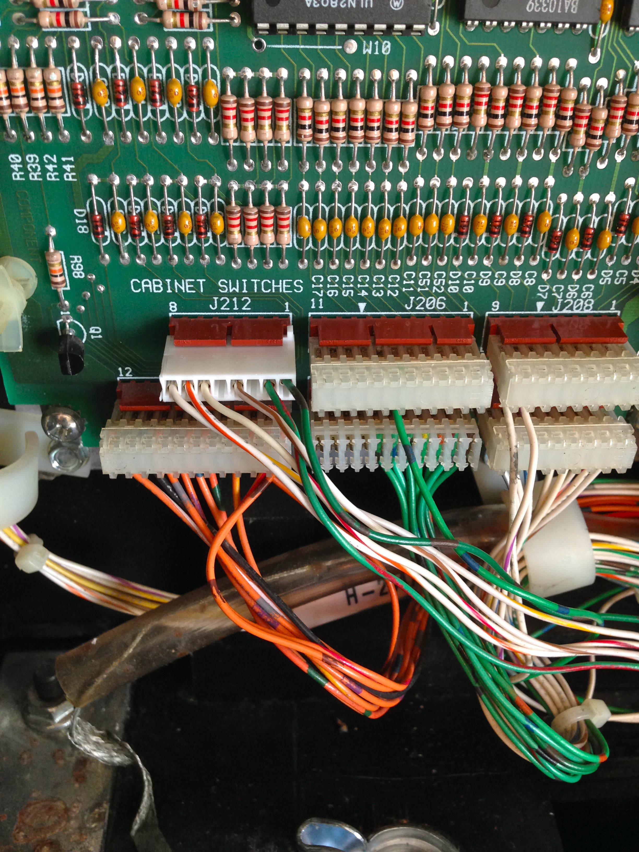
Interesting aside- note the size of the connectors (the two large ones in the above photo, one empty) for the coin mechanism. Designing a system that can take all denominations of coins in hundreds of different countries, and be configured to cost as much as the operator wants is not easy. Fully half of the large configuration system in the software is dedicated to building custom charts of cost structures for charging players to play in various different ways. Some engineer was tasked with designing this important system, and it was probably a thankless job.
In any case, no problem with our first harness. The next potential weak link in the chain is the diode. Each switch in a switch matrix needs a diode in series with it. These diodes prevent cross-talk between switches on the same row and column, and it’s what allows the CPU to read one switch at a time, even though they’re all connected to each other. These diodes can weaken over time, and start to leak current. This leakage can cause intermittent switch problems like we’re seeing here.

The schematic tells us which diode(s) could affect our interlock circuit. The diodes are labelled on the PCB, so this is an easy test.
A quick probe on all the diodes connected to our switch circuit (using the diode test function on the multimeter) showed no problems. Another way to double check the diodes is to test the operation of other switches on the same row and column. The manual has a diagram of the entire matrix. I tested a couple of switches in the same row, and a couple in the same column as our troublesome interlock. All the diodes are working fine.
The next link up the chain is a gnarly one. It’s the harness that runs from the Coin Door Interface Board to the CPU Board. It’s about eight feet long, and buried in a huge morass of wiring inside the machine. Luckily, the schematic tells us which connector on the CPU board is the other end of this harness, so we can check that and determine if there’s something in between that is failing.
Well, here’s where the story comes full circle. As soon as I found the connector on the CPU board for the other end of that harness, I laughed out loud. It was the one where I’d found all that corrosion just the other day. This was surely our culprit. Nothing causes an intermittent connection quite as effectively as battery electrolyte corrosion.

Sure enough- that’s all kinds of corroded. This connector is likely toast.

Here’s a closer look. You can see the black and green corrosion all around and inside the pins. This sure looks like our Patient Zero.
It would be nice to be sure this is the problem by bypassing the harness and testing again. However, because this is a switch matrix harness, all the wires in it need to remain connected at all times (unlike the tilt-bob situation earlier). That means to bypass this, I’d need to effectively build a new harness. That’s more work than simply replacing this connector, so I’m opting to do that and see what happens. I think we have more than enough evidence here to suspect this connector, so this isn’t a blind attempt at a repair.
The connectors used in these machines are called Insulation Displacement Connectors (IDC). They are great for manufacturing, because they are very fast to assemble. The connector has a V-shaped cutting blade inside each pin, and the wire is pressed into it from above. The V cuts the insulation, and bites into the strands of the wire, forming a solid, gas-tight seal at two points. They are a good compromise of cost vs. reliability, but they are no match for corrosive chemicals from a leaking battery.
Rather than put another IDC connector on there, I’m opting to replace it with the equivalent Molex. Molex connectors are strong, very reliable, and very serviceable. They’re more work to put together than IDC, but that’s not a problem for a hobbyist like us!
To work with Molex, you will need a Molex crimper. Nothing else will do. I would go one step further and say you must have a ratcheting crimper. Doing this with anything else is seriously asking for trouble on connectors this small. Run, do not walk to your browser, and buy the Tool Aid Ratcheting Crimper with interchangeable dies. You can get it on Amazon, or elsewhere. It’s very reasonably priced, great quality, and the entry-level kit comes with all the basic dies you’ll ever need. On top of that, the Tool Aid people have awesome customer service. Do us all a favor and support businesses like that! To crimp square Molex pins, you need Tool Aid die 18937, which is not included in the basic kit, but can be ordered separately (from Amazon, or direct from Tool Aid, with a phone call). Tooling yourself up for Molex is well worth the small upfront investment. You can build harnesses for all manner of projects very cheaply once you have the crimper. My Tool Aid crimper has singlehandedly wired two race cars, my arcade control panel, parts of my house, and countless other things. It’s one of my favorite tools, and if you don’t buy one, I’ll kick a puppy right this minute. Don’t make me do it!
Molex crimps are very strong and very reliable if done properly. Technique and the right tool are everything here. Do not take any shortcuts. Take your time, use the right tool, and it will go very smoothly. The final connector will outlive whatever machine or device you put it in.

Here’s a Molex pin, and a sample wire I’m going to attach to it. Note the two crimp areas. The upper one holds the wire, the lower (larger) one holds the insulation. You must strip the right length of wire (as shown), and position it correctly. The crimping of both the wire and insulation to precise amounts is the magic of this process.

This is what the crimper looks like. Note the two “levels” in the die. The “deeper” one crimps the large area around the insulation. The “shallower” one crimps the wire.

Here’s a connector positioned in the jaws, ready for a wire. The “female” (top in this photo) side of the die is what folds the blades around and presses them down against the wire and the insulation.
Do some practice crimps if you’ve never done Molex before. Everything has to be lined up exactly right for it to work. This is also why you want a ratcheting tool. You can place the pin in the die (as shown above) and ratchet down a couple of clicks to hold it in place. Then insert the wire, and ratchet the rest of the way. Otherwise you need three hands, and have little hope of getting a well-aligned crimp. Furthermore, the crimp has to be just the right tightness. Too loose, and the connection isn’t gas-tight. Too tight, and the wire will be weakened and fail prematurely. The ratcheting tool crimps perfectly every time with no guessing.

Here’s a proper crimp. The wire is pinched up front, and the insulation is crimped more lightly in the back. This has a gas-tight electrical connection, and a mechanical strain relief, all in one.
Note that solder is not (and should not be) involved in any part of this process!

Once crimped, you simply push the connector in to the back of the housing. It locks into place, but can be removed at any time by depressing the locking tab with a screwdriver (using the slot in the plastic housing).
So where do you get all this Molex stuff, anyway? I find it easiest from Mouser. Mouser’s site can be very intimidating, but here are the part numbers for the relevant Molex bits. Put these into the search box to get what you need. The bold “12” in some of the part numbers is the number of pins in the connector. It’s always two digits, so substitute “08” for 8 pins. The larger 0.156″ stuff is used on power connectors, and 0.100″ is used on logic signals.
- 0.156″ connector housing : 26-03-4121
- 0.156″ locking headers (breakaway) : 26-48-1155
- 0.156″ pins (Trifurcon, the good ones) : 08-52-0113
- 0.100″ connector housing : 22-01-3127
- 0.100″ locking headers : 22-23-21221
- 0.100″ pins : 08-50-0114
If you can’t get enough technical information on the physics of mechanical connectors, this site has even more detail. Note that some of the Mouser information is out of date, but the general information there is great.
Once the Molex process is understood, it’s simply a matter of pulling the wires out of the old IDC connector, cutting off any damaged end on the wire, stripping, crimping, and inserting the new pin. Move one wire over at a time to make sure nothing gets mixed up.

Almost done! Out with the old, in with the new.
Tah dah! Shiny, new and reliable!
I had a little bit of trouble with wire length on this job. A couple of the wires in the harness were barely long enough for the old connector, and putting a new one on makes them a bit shorter still. I had to loosen the harnesses a ways back from here to find some slack. Hopefully I won’t have to do this again, because there’s no more slack to be had. I suspect this connector had been worked on before, because normally there’s enough slack to do this kind of job a couple of times. If it needs doing again, wires will probably have to be extended.
There was some corrosion on the header pins as well. There’s a judgement call here- do I pull the CPU board and replace this header? This is a question of risk-reward. There are a dozen connectors and other things attached to that board. Pulling them all out to extract the PCB risks causing damage to something. The corrosion on the pins was very minor, so it may not be worth the risk to pull the board. Not to mention, there’s risk with desoldering and resoldering a header. I could damage something on the board that would have been fine if I’d left well enough alone. I opted to leave the old header in place, clean it up, and see how it goes for now. If the connection is still intermittent, I’ll take the next step and pull that board.
Well, the good news is, Johnny now seems to be fighting fit once again. I left attract mode running for 20 minutes with no signs of interlock warning, and I played several games as well. There’s no sign of any trouble at all from that connector now. Huzzah!