Category: Hacks
Electric Steam Boiler – Heads
Empowering the heads to do their jobs
Last time we roll-formed some copper stock to form the heads, and that was pretty cool. We have a few more operations to do on those pieces, and we need to make all the head-related accessory parts for our boiler.
First up are the stays. A “stay” a very steam-engineer word that usually means “a rod that keeps something else from exploding”. In this case, the something else is our heads. Thus these are “head stays”. The main body of the boiler is a cylinder, which is an inherently strong structure. Circles are really good at containing pressure. However, the heads are flat at the ends. They are a theoretical weak point in the structure. As I’ve stated before, I think Mr. Johnson’s boiler design is rather overkill for the 50 psi working pressure it will see, but I also acknowledge that no part of me is a mechanical engineer and I know basically nothing about pressure vessel design. I’m taking his word that these head stays are necessary. The head stays take the form of four copper bars that run the length of the interior, threaded into brass bosses in each head. This ties the heads together and also ensures the pressure isn’t being contained solely by the braze joints on the heads.

I purchased ¼” copper bar stock remnants from eBay. They’re quite lovely! Copper is a very attractive metal, though a bit spendy and tricky to machine.
As I’ve mentioned before, eBay is my go-to for metal stock in small amounts these days. Thanks to flat-rate USPS shipping boxes, most sellers offer free shipping, even on rather substantial chunks of steel and iron. The other day, I received a 20lb steel bar in a flat-rate envelope. Roughly 47 envelope molecules survived the journey, but the 20lb steel bar was fine because it’s a 20lb steel bar. I feel bad for everyone else’s mail in that vicinity, though.
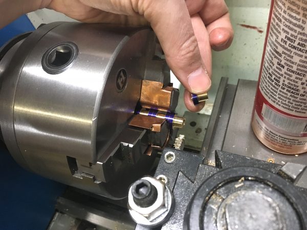
The first task for our lovely copper stays was to thread the ends ¼-20 for the mounting ferrules. Threading copper is really difficult, however. A threading operation involves a lot of tool pressure. The die is cutting multiple threads at once, and it relies on the strength of the previously cut threads to pull the die forward as it cuts new ones. Copper is highly resistant to being cut this way, and isn’t quite strong enough to push the die forward through itself. So it’s both too tough and too weak, in the exact wrong ways. My solution to this was to turn the ends of the bars 5 thou under-size, chamfer the ends generously (to help the die start), use lots of cutting oil, and apply a lot of forward pressure on the die. Even with all that, there are decent odds the threads self-destruct partway through if the die gets hung up.
Another option would be to single-point cut these threads rather than using a die. However, these bars are very thin. Probably too thin to hold up well to the high tool pressures needed to machine copper.

It was no picnic, but I did manage to get ¼-20 threads cut on each end of each stay.
Next up are the ferrules. These are brazed into holes in the heads, and the stays are threaded in to them. We need eight of them, so it’s mass production time.

I marked out all the diameter changes on a batch of four ferrules. I added an additional zone between each one, the exact width of my parting tool.
I’ve mentioned this parting-tool technique previously, but it was extra useful here. Using a wide parting tool, you can plunge into the work to the depth needed for final diameter, and make a note of the dial reading on the cross-slide. You can then cut the rest of that diameter by winding out past the backlash, then coming back in to that same dial reading on each ferrule. It’s the poor-person’s DRO.

Repeatability is what machine tools are all about. Using the same dial reading each time, the diameters are formed by plunging over and over again. This is a very efficient way to turn out a batch of shouldered bushings.
I did two batches of four. I didn’t want to do a batch of eight all at once, because the unsupported stock area in the lathe got pretty large, and the parting-tool-plunge technique requires good rigidity in the setup. This might be a good use-case for a follow-rest!

With the profiles cut, I then tapped all four at once as well.
Profiled and tapped, we can now part off each one using the waste zone we marked between each ferrule.
The final step in our production line- each one gets parted off and thrown in the finishing bin. If it was 1890, we just earned ourselves 4 cents! Isn’t pre-union life great? Wait, no, piecework is a miserable existence.

Here’s how the stays work. The ferrules are brazed into each head, and the rods thread into them. Four total, spaced roughly evenly around the head. This should be a very strong design!
At this point, you might be wondering about why the stays are copper, instead of brass like everything else. This is open to debate, and the original article by D.E. Johnson doesn’t say. The general belief about this sort of thing is that copper is safe for steam, and yellow brass is less-so because of dezincification. The theory goes that steam can leech zinc out of yellow brass, leaving the fitting porous and weak, and thus a potential failure point.
This is one of those things that is technically true, but irrelevant at small model scales. Yes, for a larger steam engine running north of, say, 150psi, there are regulations governing what types of materials to use in pipes and fittings. You probably shouldn’t make the whole boiler out of brass at any scale, although people do. There are some brass fittings in this design that are in contact with steam, so it could be a point of concern. However, the flip side is that using brass fittings in small low-pressure boilers is common practice, and model boilers are not murdering people by the thousands. For further antidote to any imminent concern-trolling, the design here is by a man with plenty of boiler making experience, and published in a reputable magazine all about making steam boilers. If this thing was a death trap, we’d know about it. Finally, note that dezincification mainly happens when using mineralized water in the boiler, and I’ll be running only distilled in this one (mainly to reduce scaling problems).
So, is dezincification of yellow brass in a steam environment a real problem? Technically yes. For us, no. If you’re building a big high pressure boiler, stick to bronze fittings and cast iron pipe. If you’re building a fun little one, relax and get on with your life, already.
Okay, back to our heads! Each head serves an additional important purpose. One holds the electric heating element, and the other holds the thermoswitch that controls it. They are both immersion devices, and we need mounting bosses for each. I opted to buy suitable bronze pipe fittings for this, since it was easier than trying to make them. The heating element in particular uses a very large NPT thread which I didn’t want to attempt to make myself.
For the heating element, I bought an adapter fitting from one pipe thread type to another. The “other” didn’t matter, but the inner thread matches my heating element. Bronze is pretty expensive, so buying a commercial casting like this saves a lot of material and thus hard-earned Patreon farthings.

Here’s the large bronze casting for the heating element. It’s functional, but a pretty dreadful casting. You get what you pay for, I guess. I opted to clean it up a bit. I faced the front, to start.

I then flipped it around and turned the outer threads off, since we don’t need them.

I then cut it down to an appropriate length, and we have our mounting boss!
The poor quality of this fitting would come back to haunt me later, though. I had difficulty getting these threads to seal. More on that in a later article. Anyways, I repeated this process with a much smaller bronze casting for the thermoswitch.

You might be asking why I have two of these? The first one was of such poor quality that the thermoswitch wouldn’t even thread into it. The threads weren’t even salvageable in a way that I would trust them to seal, so I ordered a second one. The junked one will find new life as something else someday. The junk pile taketh and the junk pile provideth.
Note that all of the small head fittings were turned to a couple thousandths over size for the holes in the heads. I then used a tapered hand reamer to open up each hole slowly until the ferrule/boss/etc was a very close fit. This should help make brazing cleaner and easier later.

Because each ferrule is handed fitted to its respective location, I labelled everything to keep track. Note that the copper is still blackened from the annealing needed by the roll-forming operation. There’s little point in cleaning it up until later, since it’s going to keep getting dirty.
With the two large bosses made, it was time to make holes in the heads for them. The heater element boss is particularly interesting, because it’s much larger than any drill bit I have. This would be a good operation for a boring head in a milling machine, but I also possess neither of those. When all you have is a hammer, you view every problem like a nail. When all you have is a lathe, everything starts to look like a faceplate operation. You’ll see what I mean shortly.

I started by laying out where I wanted the big hole to be. I made a couple of attempts at it, then punched the center when I was happy.
The only way I have to make a large hole is the boring bar on the lathe, so we needed a setup for that. Not really planning ahead at this point, I started with the four-jaw chuck. First we need to make a hole big enough for the boring bar to get started.

I clamped the head gently in the four-jaw chuck (to avoid damaging the rolled edges), and dialed it in using a dead-center on the punch mark made earlier.

I then center-drilled and drilled up to my largest bit size. I worked up in drill size, since the head is clamped lightly to avoid deforming it.
Now we’re ready for the boring bar. It was at this point that I realized I couldn’t go any further with this setup. There wasn’t room to clear the jaws with the boring bar– the hole was too big. There also wasn’t room to get sacrificial material between the workpiece and the jaws, so it was time for the faceplate.
The setup I came up with involves sacrificial aluminum strips threaded to accept short mounting screws. The strips are mounted to the faceplate with hardware smaller than the faceplate slots, which allows me to adjust the piece to get it centered.

I put a dial indicator on the inside edge of the hole I drilled in order to get it back on the same center it had in the four-jaw set up from the previous operation.
This setup was very time consuming, as I had to gently tap the piece around until it was dialed in. I didn’t have the luxury of any jaws to adjust, and the directions of motion available here are not orthogonal. All the mounting plates are at weird angles, so I had to learn how tapping each one affected the run out, then use that knowledge to dial it in. It was tedious, but I only had to do it once! This would have been immensely easier if I had started with the faceplate, since I wouldn’t be trying to indicate in an existing hole (with a gap in it, no less). However, it goes to show that with some sweat and ingenuity (in that order), you can recover almost any situation in the machine shop.

The setup was tricky, but the end result was brilliant! The boring bar worked like a champ and the large hole is exactly where I wanted it.
I used the telescoping gage to get the diameter half a thousandth larger than the boss I had turned from the crappy casting. Just enough for a snug slip fit.

A perfect fit! Note that the boss is partly covering two of the holes for the stay ferrules. I filed down the sides of this piece for clearance. It doesn’t need to remain a perfect hexagon. As long as there are flat sides, we can grip it with a wrench as needed.
With that, our heads are ready for assembly! We’re getting perilously close to being able to assemble this boiler now. We’ll be making steam (maybe) before you know it, so stay tuned!
One last thing- Blondihacks is now on Instagram! Follow me there for sneak peak photos of upcoming projects. You can find that link (as well as Twitter) any time at the top of the site.